
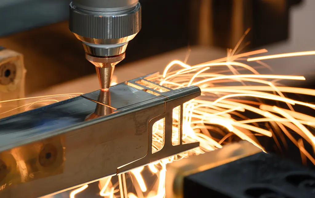
A tube laser can bring profiles, holes, slots and joint features into one programmed cutting operation. For some components, further consolidation is possible through bevel cutting or dedicated drilling and tapping equipment within the same system.
The buying decision is whether those operations improve the complete route to an accepted component. Start by listing every step on the drawing and identifying which steps the proposed configuration can complete to the required standard.
Understand what each process does
| Configuration | Potential benefit | What needs proving |
|---|---|---|
| Laser cutting only | Combine cut-to-length profiles, slots, notches and suitable holes without separate marking out. | Feature accuracy, cut condition, internal spatter and any holes that still require mechanical finishing. |
| Laser cutting with bevel | Produce suitable angled edges, joint geometry or weld preparation during cutting. | Angle, root face, access, wall-thickness limits, fit-up and the required weld preparation. |
| Laser cutting with drilling | Complete suitable mechanically produced holes without a separate setup. | Tool access, diameter, roundness, finish, positional tolerance, clamping and swarf clearance. |
| Laser cutting with drilling and tapping | Produce suitable holes and internal threads in the programmed route. | Thread engagement, thread gauge results, tool life, wall support and tool-break recovery. |
These are configuration choices. A bevel head does not provide mechanical drilling or tapping, and a laser-cut hole is not a tapped hole. Confirm every required capability against the quoted equipment, software and part geometry.
Decide which holes can be laser cut
Many clearance holes and shaped features can be produced by the laser if the result meets the drawing. Holes with tighter requirements for diameter, roundness, finish or thread preparation may need a mechanical operation.
Ask whether a hole is laser cut to final size, laser cut undersize for subsequent machining, or drilled directly. Do not assume that every laser-cut hole is suitable for tapping without additional preparation.
Where thermal or friction drilling is proposed, clarify the process. Forming a collar in the tube wall is different from conventional drilling and can affect available thread engagement and the component design. It needs its own part approval.
Assess bevel cutting against the joint
Bevel cutting can reduce separate edge preparation on suitable parts. The useful result is a joint that meets the fabrication requirement, including angle, root face, access and fit-up.
Trial the intended tube profile and wall thickness. Check features near corners, the weld seam and other restricted areas. A headline bevel angle does not prove that every edge on the component is reachable or suitable for the intended weld procedure.
Compare complete process routes
For the existing route, record sawing, marking, cutting, drilling, tapping, bevelling, deburring, inspection and transfers. Include setup, queues and the time spent locating the part again at each station.
For the consolidated route, include tool changes, mechanical processing time, lubrication, swarf removal and routine servicing. Adding drilling and tapping can occupy the tube laser for longer. That can still improve the job if it removes enough separate handling and setup, but it may be less attractive when only a small share of work needs those operations.
Compare both routes using the same quantity of accepted parts. Consider the effect of downtime too: when several operations share one machine, a fault may interrupt more of the production route.
Sample-part acceptance checklist
Agree the following points before the demonstration. Use several normal production parts and at least one difficult component, with an approved drawing revision and measurable acceptance limits.
- Stock: use the specified grade, profile, wall thickness and realistic surface condition. Include expected straightness and seam variation.
- Handling: demonstrate loading, support, clamping and unloading at the intended stock and component lengths. Confirm chuck arrangement, minimum and maximum section sizes and weights, access near the chucks, clamp marks and deformation.
- Material yield: record residual length and usable yield with the proposed nesting strategy. Confirm remnant handling and whether any last-part restrictions affect the drawing pack.
- Seam and orientation: where weld-seam recognition or automatic orientation is required, demonstrate it on representative stock and establish what happens if recognition fails.
- Dimensions: measure overall length, feature positions, hole sizes and relationships between faces against the drawing datums.
- Cut quality: inspect burrs, edge condition, internal spatter, opposite-wall damage and any cleaning needed.
- Bevel: check angle, root face, consistency and fit-up on every relevant edge. Confirm suitability for the intended weld preparation.
- Drilling: establish the actual hole-making method and measure diameter, roundness, position and finish as required.
- Tapping: verify thread size, pitch, effective engagement and the specified GO/NO-GO gauge result. Add a functional or load test where the component specification requires one.
- Repeatability: measure parts across the agreed run, including after a stock reload and tool change.
- Cycle and labour: time the complete route, including setup, tool changes, inspection, sorting and manual finishing.
- Recovery: demonstrate the agreed response to a failed hole, broken tool or rejected component, including how the replacement part is identified.
- Next operation: take sample parts through the intended assembly or welding stage and record any additional preparation.
- Sign-off: retain measured samples, inspection records, cycle data and the exact demonstrated machine and software configuration.
Choose the operations your parts justify
A laser-only route may be the most economical choice when profiles and clearance holes dominate. Bevel, drilling or tapping options deserve closer attention when they remove recurring, costly secondary operations and pass the same acceptance requirements.
The aim is a shorter, more reliable route to a usable component. Count the handling and setups removed, then confirm the work that still remains.
Review your tube processing route
Explore Selmach’s Morgan Rushworth tube and section laser range, then share representative drawings with our team. We can help assess cutting and bevel requirements and establish which secondary operations need separate equipment or a specifically verified configuration.
Published 29th October 2026