
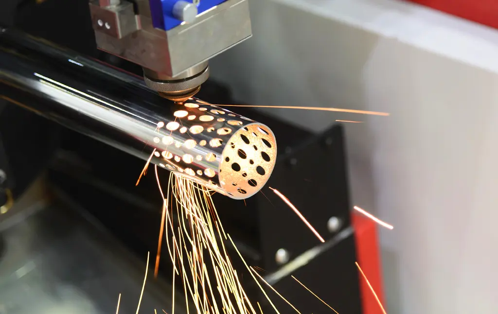
Tube laser cutting can combine several preparation operations in one programmed process. Its wider value often appears at the welding bench, where accurately positioned features can reduce marking out and make components easier to assemble.
Selmach’s tube laser productivity guide covers general processing benefits. The next step is to review how the component design helps the people who fit, locate and weld the assembly.
Start with the assembly sequence
Choose a regular assembly and record how it is built. Note where the team measures, marks, clamps, checks orientation or adjusts the fit between components.
These steps can reveal opportunities for laser-cut locating features. The aim is to remove unnecessary uncertainty while preserving the requirements of the finished assembly.
Work from the approved design and actual fabrication route. A feature that looks useful in CAD may be inaccessible during assembly or interfere with a fixture, fastener or weld.
Give tabs and slots a purpose
A tab-and-slot arrangement can help locate one component relative to another. It can also make an incorrect orientation easier to spot when the features are deliberately asymmetric.
The fit must be designed for the material, cutting process and assembly method. There is no single clearance for every tube size, wall thickness and joint. Validate it with representative parts rather than assuming a nominal drawing fit will behave as intended.
Locating features are not a substitute for checking alignment. The assembly still needs the fixtures, inspection and controls required by its design and production process.
Review end profiles and mating surfaces
Shaped tube ends can reduce manual preparation where the machine and cutting head can produce the required geometry. Review the mating surface, cutting access and condition required before welding.
A close fit may improve consistency, but the joint needs the gap and preparation specified for the welding process. Designing every connection to fit as tightly as possible can create another problem at the welding stage.
Confirm bevel or angled-cut requirements for the selected equipment. A general claim about tube cutting does not establish the capability of every machine configuration.
Add useful identification
Part identification and orientation information can help distinguish similar components. Discuss whether the equipment can produce suitable marking features and how the marks will remain visible through production.
Agree the purpose and position of identification. Avoid placing it where it interferes with a critical feature, required finish or later operation.
Keep drawing and programme revisions aligned. A kit containing parts from two revisions can fit together incorrectly even when each component has been cut accurately.
Consider the consequences of extra features
Tabs, slots and access holes change the component. The designer should review their effect on section behaviour, joint requirements, weld access and the service environment.
Some details may trap finishing material or create areas needing extra cleaning or inspection. Others may be difficult to cut consistently in the chosen position. Review these issues during design rather than after the first batch.
Where a bend connection or partially cut feature is proposed, establish how it will be formed and controlled. Its suitability must be demonstrated for the particular material and assembly.
Measure the result at the bench
Compare the existing and revised assembly using the same acceptance requirements. Record preparation time, fit-up time, fixture changes, adjustment work and first-pass acceptance.
Do not judge a redesign only by the laser cycle. A slightly longer cutting programme can still be useful if it removes substantial marking and fitting work downstream.
Equally, a locating feature may provide little benefit if the assembly already uses an efficient fixture. The practical result should determine whether it stays in the design.
Prove one assembly first
Select a repeat assembly with a clear preparation or fit-up problem. Produce a small trial, involve the people who will weld it and record improvements and remaining difficulties.
Selmach can help assess the tube and section laser range using drawings and sample work. For mixed assemblies, review the tube and sheet workflow so complete kits reach welding together.
Published 13th October 2026