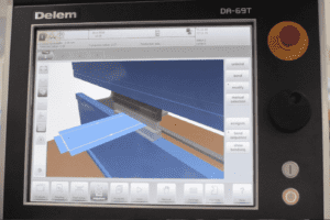
The Delem 69 Touch offers 2D and 3D programming with automatic bend sequence calculation and collision detection. Full 3D machine set-up with multiple tool stations giving the feedback you need on product feasibility and handling.
Follow our easy to understand guide to get the most out of it, safely, quickly and simply.
Firstly turn on the isolator and wait for the display to load up, then press the reset button and ensure that acas is at zero, key position is at number two and both the emergency stop and foot pedal are fully reset.
Referencing the machine is the next important step, selecting the product option will bring up earlier drawings as shown in the video, from here you can also check your tool set-up, bend sequences and if the program looks good then select auto, then start.
The R axis and X axis, as well as the Z1 and Z2 axes will now reference, when that is complete, pressing the up pedal will reference Y1 and Y2. You can now perform a speed check for your laser bars by pressing the down pedal.
Drawing a new 3D product
Select new product and allocate your product’s number or name, then enter your thickness, material type, bend length, whether you need to work inner or outer, then radii and bend allowance as calculated.
Finally select the accept option and this will bring up the drawing package as shown. Much like a mobile device or tablet, adding bends and sizes is a simple case of dragging your finger where you need it, changing figures, bends etc as needed. Adding another bend in 3D is equally easy using the options in the vertical left hand menu, when you are happy, select the tool set-up option.
Delete any configurations from previous jobs in the tooling setup and auto-select your new configuration, this can select the length of the tooling required we have also added another adapter in the video which again auto-selects the correct length. Now you are ready to pick your bend sequence as shown. You can also view and move the back gauge probes and move them on screen as needed, selecting accept when you are happy.
You will notice that many different views can be seen, from full graphic to individual bends and 2D, at this point your machine is ready to run, as you can see in the video.
You can also view all the different programs used on your machine, in our example some have been entered numerically, while some have also been done graphically as can be seen by the icons. You can import DXF and 3D programs and once stored they are all easily retrieved for future reference from the product screen, just as adding a new product is also quick and simple as described above.
It is important, when selecting your bend sequence to view the various stages to identify any issues in the sequence itself, as you can see in the video bends 3 & 4 are in an incorrect order, the controller will notify of any issues with a red icon instead of green. Any problems are easily rectified by selecting bend sequence, then ‘new’ then un-bend everything. Then perform the bend sequence again (virtually) the controller will identify and rectify any issues and adjust the bend sequence accordingly, with each sequence getting the green icon. As seen in the video each bend can be seen in 3D to ensure all is well…
If you need to modify the bend sequence, the bend sequence page allows simple viewing of each stage, with the option to modify each and even swap the order if necessary.
The programming page is the screen where you can shift the gauge to prevent your workpiece from dropping down (where the bends allow it based on the controllers programmed sequence).
Even if you are running a program graphically, each bend can be adjusted by speed, method, opening of beams, dwell time and decompression. If you have a job where the backgauge is at risk of crashing you can also adjust delay times, retraction times and if you aren’t happy with where any of the axes currently are then again, those figures can be easily modified. Everything is easily adjustable, product properties can be checked and double checked and there is also the facility to make and edit notes, change tools and shift the graphical representation of the product anywhere around the 3D space.
Entering a numerical program
Simply select new program form the product screen and give the program an ID, then enter thickness and type of material. The Tool set up menu works just as intuitively, start by deleting the previous configuration and adapter then press auto-select and add adapter, then enter your bend sequence and folds as desired using the add bend option as needed then select auto and run. As you can see in the video, viewing the sequence and making adjustments works just the same as with the graphical 3D program, with the numerical values still available automatically, making adjustments and programming intuitive and simple.
For more information on the Delem 69T controller, click, tap or call us on +44 (0)1432 346 580, email [email protected] or get in touch via our website
Published 18th June 2018