The lathe is often called the “mother of all machine tools”, and for good reason. It is one of the oldest and most versatile machines in engineering, capable of performing a huge range of operations such as turning, facing, drilling, boring, knurling, threading, and more.
Whether you are an experienced machinist, a student, or someone looking to invest in new workshop equipment, understanding the parts of a lathe and how they work together is essential. Knowing the anatomy of a lathe helps you operate it safely, achieve accurate results, and choose the right machine for your needs.
In this guide, we’ll explore each component in detail, showing how it contributes to the lathe’s overall function. You’ll also find internal links to our selection of lathes so you can see these features in action.
What is a Lathe?
A lathe is a machine tool that rotates a workpiece against a stationary cutting tool, removing material to shape it into the desired form. This process is called turning, and it is fundamental to manufacturing everything from simple shafts and bushings to complex precision parts for the aerospace, automotive, and energy industries.
Modern lathes range from small, manually operated models for workshops to fully automated CNC lathes used in mass production. Despite advances in technology, the core design has remained remarkably consistent for centuries, because the basic physics of cutting and rotation haven’t changed.
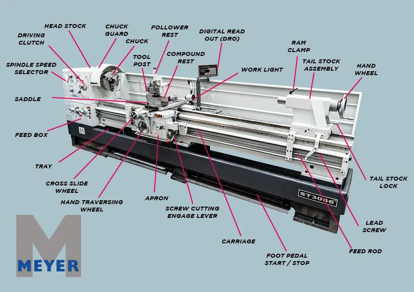
Every lathe consists of several key parts working in harmony. Let’s explore them, starting from the ground up.
1. Bed – The Foundation of the Lathe
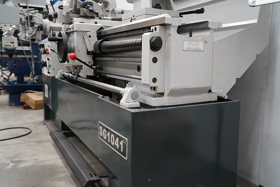
The bed is the backbone of the entire machine. Made from heavy cast iron or steel, it provides rigidity and stability, ensuring the other parts remain aligned during cutting.
-
Function:
The bed supports the headstock, tailstock, and carriage while resisting vibration. Its weight absorbs cutting forces, preventing chatter (unwanted vibration that leads to poor surface finish). -
Guideways:
The upper surface of the bed features precision-machined guideways, also known simply as ways, which are the tracks along which the carriage and tailstock slide. These must remain perfectly straight and properly lubricated to maintain accuracy over time. -
Why It Matters:
If the bed or ways become worn or damaged, precision is lost across every operation, making the machine unreliable.
2. Headstock – Power and Motion Control
Mounted at one end of the bed, usually on the operator’s left, the headstock houses the components that drive and control the rotation of the workpiece.
Key elements inside the headstock include:
-
Spindle:
The rotating shaft that holds and spins the workpiece. It is supported by high-precision bearings to ensure smooth, stable motion. -
Drive Mechanism:
Either a belt and pulley system, gearbox, or modern variable-speed drive connected to an electric motor. This lets you adjust spindle speeds for different materials and cutting operations. -
Gearbox:
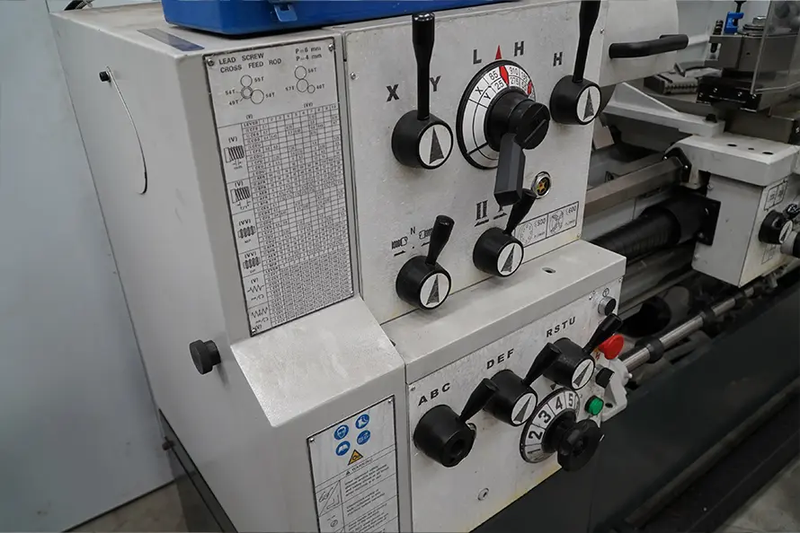
Many lathes have an integrated gearbox for easy speed selection. This is especially important when cutting threads, as precise synchronization between the spindle and carriage feed is required.
The headstock is critical to both performance and safety. A well-designed headstock provides consistent power delivery while protecting operators with guards and emergency stop controls.
3. Spindle, Chuck, and Work Holding Devices
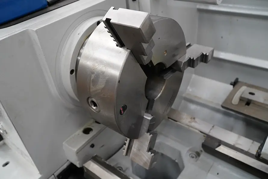
The spindle extends through the headstock, and it’s the part that physically rotates the workpiece. At the front of the spindle, you’ll find various work holding devices:
-
Chucks:
The most common type of work holding device.-
3-jaw self-centring chuck: Ideal for round or hexagonal stock where speed and accuracy are priorities.
-
4-jaw independent chuck: Each jaw moves separately, perfect for square or irregularly shaped workpieces and when extreme precision is needed.
-
-
Collets:
Used for small, precision work. They offer a very strong grip with excellent concentricity. -
Faceplates:
Flat plates with slots and holes for clamping large or irregularly shaped workpieces.
A reliable work holding system is essential for both precision and safety. Poor clamping can cause dangerous accidents and ruin the accuracy of your parts.
Browse our full range of engineering lathes to find machines equipped with versatile chuck options.
4. Tailstock – Support and Tool Holding
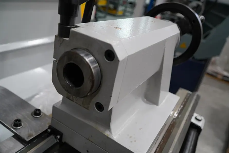
On the opposite end of the bed sits the tailstock. Unlike the headstock, it does not rotate, but it plays a crucial supporting role.
-
Primary Function:
To hold and support the free end of long workpieces, preventing deflection during turning. -
Tool Holding:
The tailstock can also hold tools such as drill bits, reamers, and taps for operations like drilling and boring. -
Adjustable Positioning:
It can slide along the bed and be locked in place at any point to suit different workpiece lengths. -
Quill (or Barrel):
The sliding component inside the tailstock body. It can be extended and retracted to advance cutting tools into the workpiece.
In precision turning, a well-aligned tailstock ensures concentric cuts and prevents tapering errors.
5. Carriage – The Tool Mover
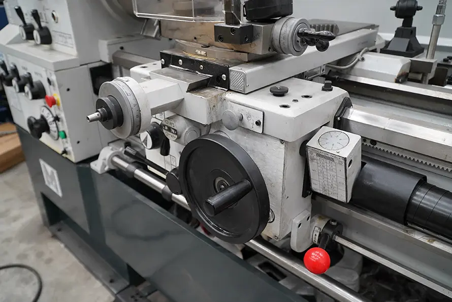
The carriage is the assembly that moves the cutting tool into position. It’s made up of several subcomponents, each with a specific role:
-
Saddle:
The base of the carriage that rides directly on the bed’s guideways. -
Apron:
Mounted on the front of the saddle, the apron houses gears and controls that move the carriage automatically via the feed rod or lead screw. -
Cross Slide:
Mounted on top of the saddle, it moves the cutting tool perpendicular to the workpiece’s axis. This is essential for facing operations. -
Compound Rest (or Compound Slide):
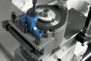
Positioned on top of the cross slide, the compound rest can be swivelled to cut precise angles, tapers, or perform fine adjustments. -
Tool Post:
The fixture that holds the cutting tool securely.-
Standard tool posts hold one tool at a time.
-
Quick-change tool posts allow rapid switching between multiple tools for greater efficiency.
-
In CNC lathes or more advanced manual machines, you might also find a turret tool post, which can automatically rotate to bring different tools into position without manual adjustment.
6. Lead Screw and Feed Rod – Automating Movement
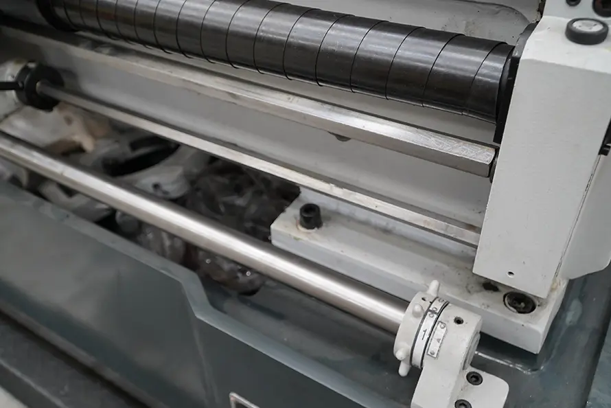
Two key shafts run along the length of the lathe to automate movement and ensure precision.
-
Lead Screw:
A precision-threaded shaft used specifically for thread cutting. When engaged, it moves the carriage in perfect synchronisation with the spindle, creating accurate screw threads. -
Feed Rod:
Provides power for general movement of the carriage and cross slide during normal turning operations.
This division of tasks prevents wear on the lead screw and maintains its accuracy for threading.
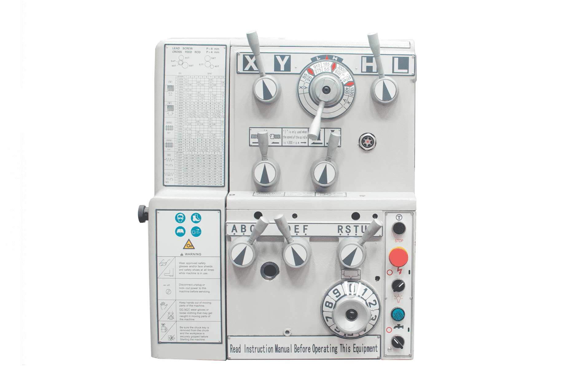
7. Gearbox and Speed Control
The gearbox, sometimes called the feed gearbox or change gear system, allows the operator to select different feed rates and threading pitches. By changing gear combinations, you can match the spindle rotation with the desired carriage movement for the specific operation.
Modern lathes may feature:
-
Lever-operated gearboxes for quick adjustments.
-
Digital variable-speed drives for smooth, stepless control.
-
Pre-programmed settings in CNC lathes for maximum precision.
Proper speed control is essential. Too high a speed can damage the tool or workpiece, while too low a speed can reduce efficiency.
8. Guideways – Precision Sliding Surfaces
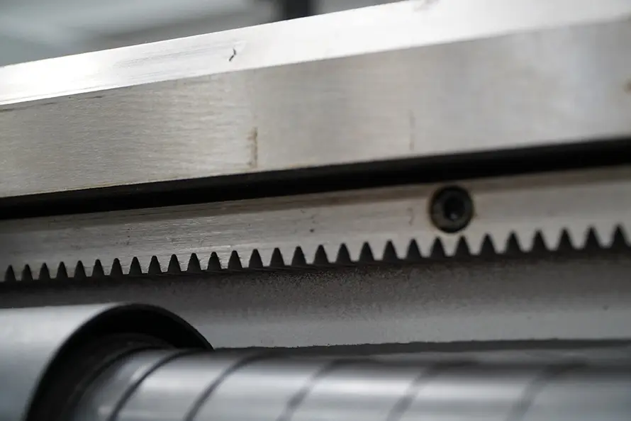
The guideways on the bed are meticulously machined surfaces that allow the carriage and tailstock to slide smoothly and accurately. There are several common designs:
-
Flat and V-shaped ways – a combination that balances stability and ease of manufacturing.
-
Prismatic or box ways – known for rigidity and heavy-duty applications.
Good lubrication and regular maintenance are vital to prevent wear and maintain long-term accuracy.
9. Chip Management and Safety Features
Metal turning generates swarf — chips of metal that must be safely collected and removed.
-
Chip Pan or Chip Tray:
Located beneath the bed to catch falling debris, making cleanup easier and preventing blockages. -
Guards and Covers:
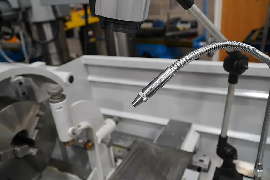
Protect operators from flying chips, rotating parts, and coolant splash. -
Coolant System:
Many lathes include a coolant pump to direct cutting fluid at the tool-workpiece interface, reducing heat and improving surface finish.
These features are especially important in high-volume production environments where efficiency and safety go hand in hand.
10. Support Structures and Base
The entire lathe must sit on a stable foundation to maintain accuracy. Most industrial lathes are mounted on heavy-duty stands or bolted directly to the workshop floor.
A solid base minimises vibration, which can otherwise affect precision and tool life.
11. Handwheels, Levers, and Controls
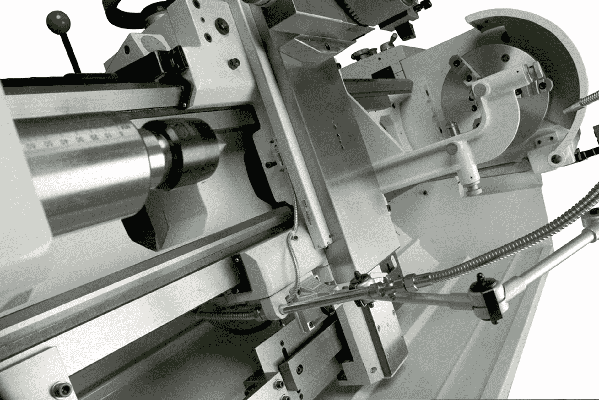
The operator interacts with the lathe via an array of handwheels, levers, and buttons, which control everything from spindle speed to tool movement.
Modern lathes may also feature:
-
Digital readouts (DROs) for precise position feedback.
-
Emergency stop buttons and safety interlocks.
-
Touchscreen control panels on CNC models.

12. Optional Attachments and Accessories
Lathes can be customised with a range of optional accessories, including:
-
Steady Rest and Follower Rest: Support long, slender workpieces during turning.
- Quick-Change Toolpost: Quickly change between assorted tools.
-
Taper Turning Attachment: Automatically cuts tapers without manually adjusting the compound rest.
-
Thread Dial Indicator: Simplifies thread cutting by indicating when to engage the lead screw.
-
Digital Readouts (DROs): Improves precision in manual operations.
The right accessories expand your lathe’s capabilities and can significantly improve efficiency.
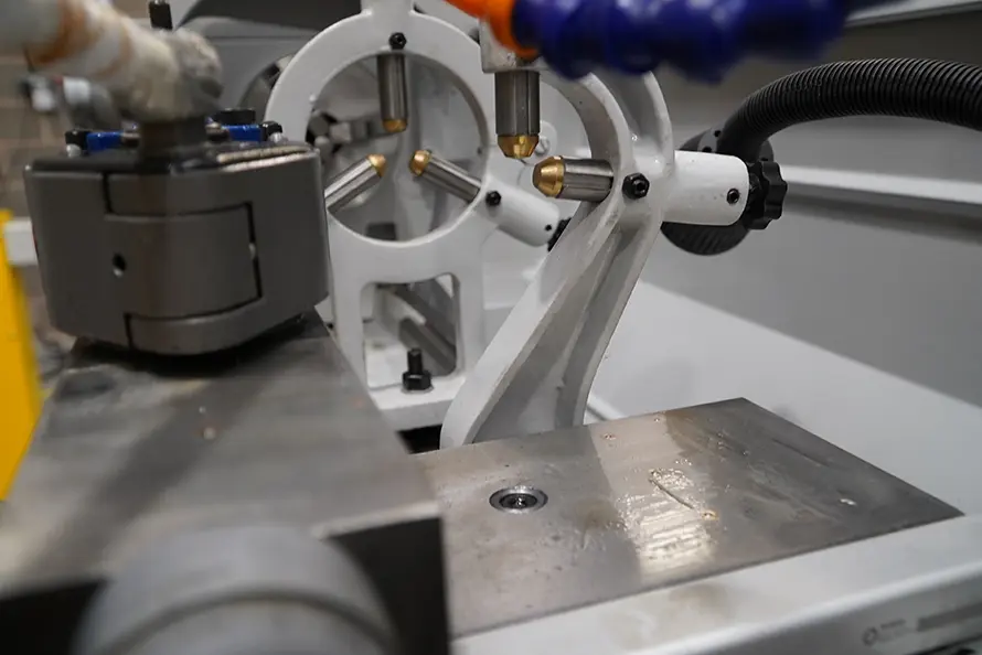
Steady (L) / Follower (R) Rest
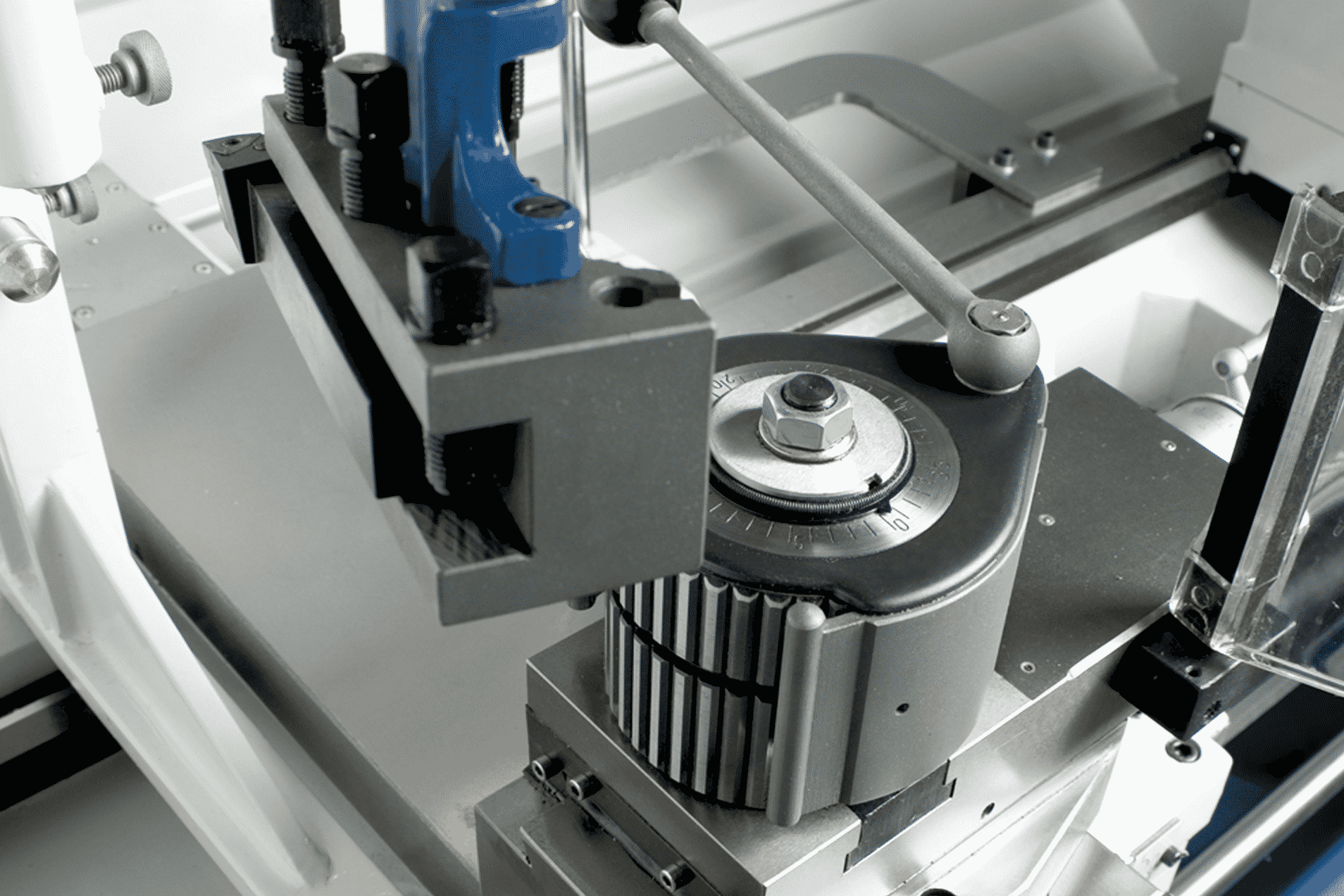
Quick Change Toolpost
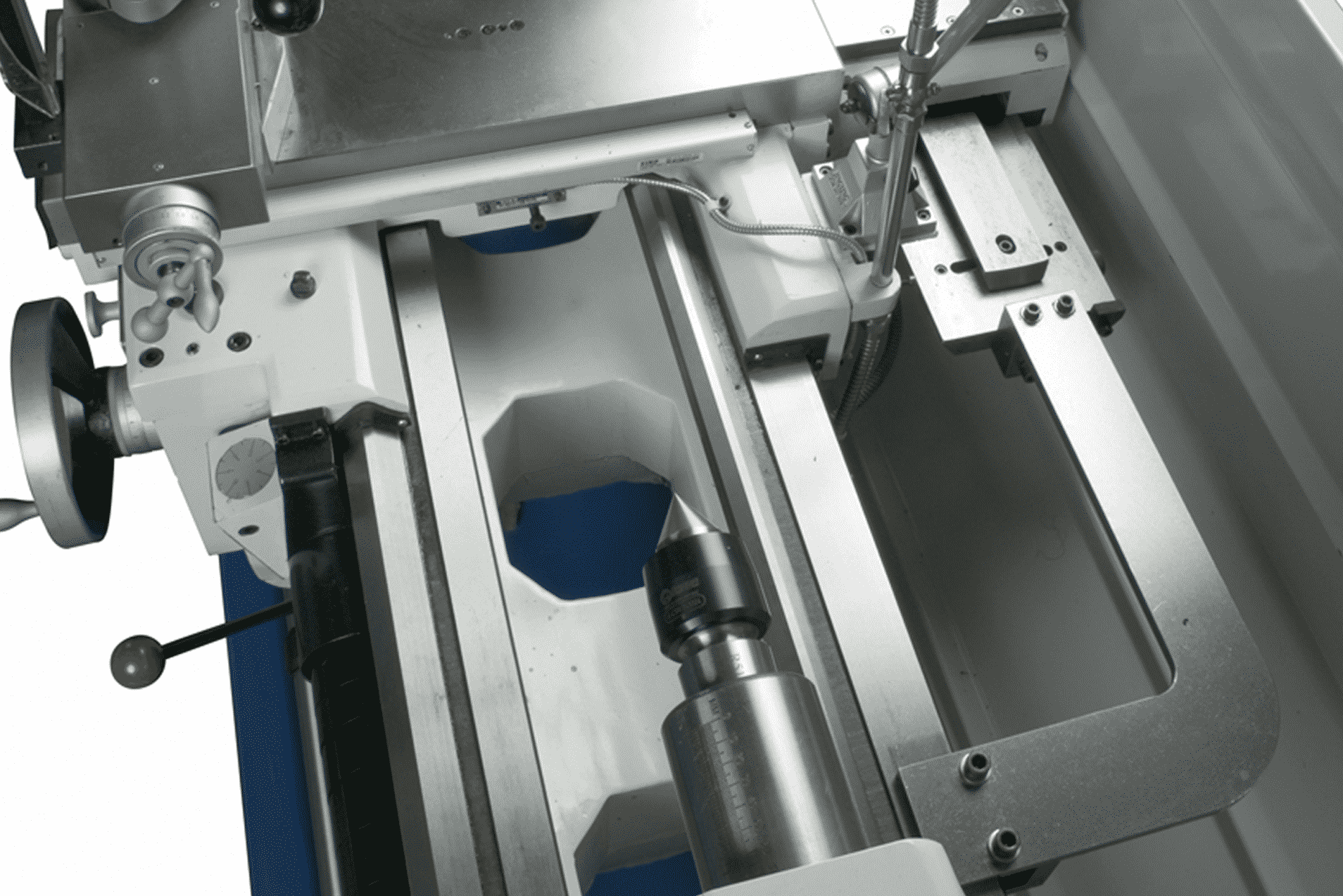
Taper Turning
How These Parts Work Together
To understand how all these parts interact, here’s a simplified overview of a typical turning operation:
-
Secure the Workpiece: Clamp it in the chuck or between centres.
-
Adjust the Tailstock: Position and lock it to support long workpieces.
-
Select the Speed: Use the headstock controls to set spindle speed.
-
Position the Tool: Move the carriage and cross slide to align the cutting tool.
-
Engage the Feed: Use the feed rod for general cutting or the lead screw for threading.
-
Activate Coolant: Direct cutting fluid at the cutting zone if needed.
-
Complete the Cut: Monitor the process, adjusting as necessary.
-
Clean Up: Remove swarf and prepare the machine for the next operation.
Each component plays a vital role in this cycle, working together to deliver precision and repeatability.
Choosing the Right Lathe
Understanding lathe anatomy helps you select the right machine for your workshop. Consider:
-
Size and capacity – Length between centres, swing over bed, and spindle bore size.
-
Manual vs CNC – Manual for flexibility and lower cost, CNC for speed and automation.
-
Tooling and accessories – Quick-change tool posts, DROs, coolant systems.
-
Power and speed control – Variable speed drives vs fixed gearboxes.
Selmach Machinery offers a wide range of industrial engineering lathes suitable for everything from small workshops to large-scale production. Our expert team can help you match the machine to your exact needs.
Maintaining Your Lathe
A lathe is an investment, and proper maintenance ensures it performs at its best for years to come.
-
Keep guideways clean and lubricated.
-
Regularly check alignment of the tailstock and carriage.
-
Replace worn chucks or bearings promptly.
-
Inspect belts, gears, and electrical systems.
-
Keep swarf cleared from the chip tray and moving parts.
By caring for each component, you maintain overall accuracy and reliability.
Conclusion
A lathe may appear complex, but when you break it down into its individual parts, it becomes much easier to understand and operate. From the heavy-duty bed to the delicate precision of the tool post, every component plays a role in turning raw material into a finished product.
Whether you’re learning machining techniques or upgrading your workshop, knowing the anatomy of a lathe gives you the knowledge to work safely, efficiently, and with confidence.
Explore our full range of engineering lathes to find the perfect machine for your operations.
Published 24th September 2025


